University of Maryland
Baja Terp Racing.
Baja SAE
Introduction
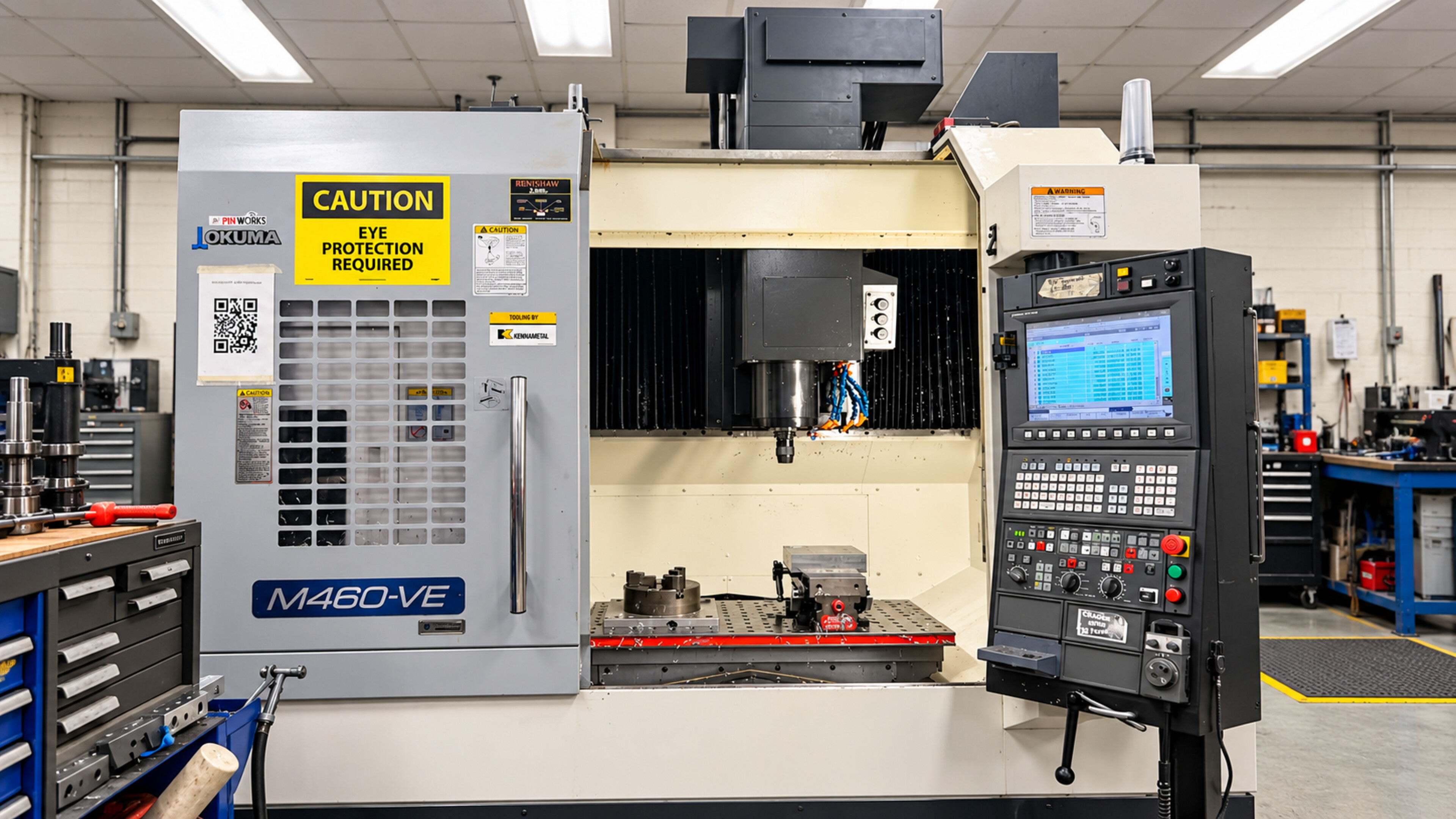
Baja Terp Racing is one of UMD’s largest student engineering organizations, where members design, build, and manufacture a new off-road vehicle from the ground up each year for the annual Baja SAE competition. I joined the Chassis and Manufacturing subteam and was selected to receive hands-on training in Computer Numerical Control (CNC) machining and manual milling. On the CNC mill, I machined several components from 6061-T6 aluminum, including the front and rear uprights, front and rear hubs, pedals, clevises, and steering rack. Using the manual mill, I fabricated tabs and jigs for assembling the car’s chassis.
CNC Machining · 6061-T6 Aluminum
Rear Hub
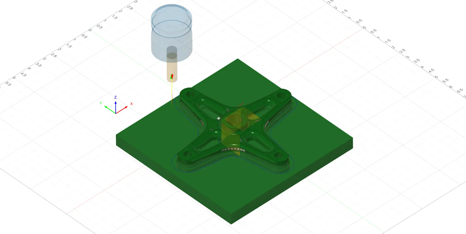
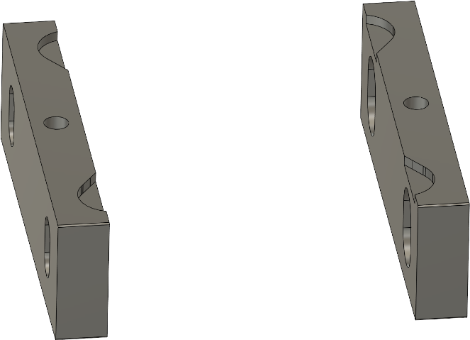
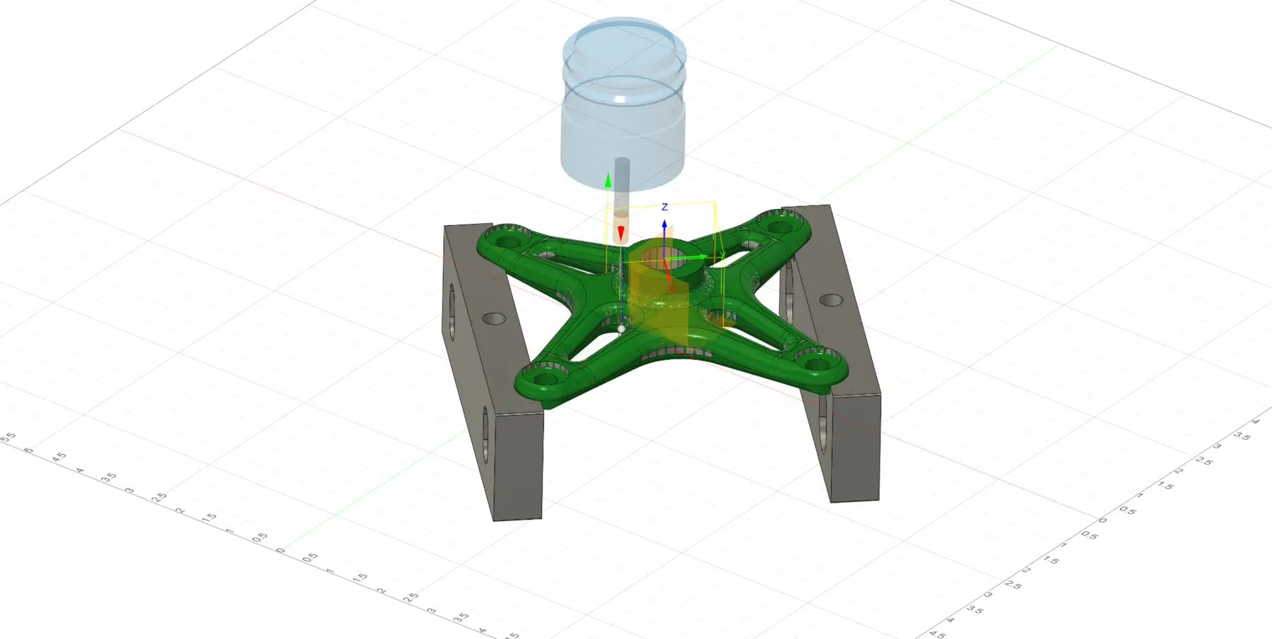
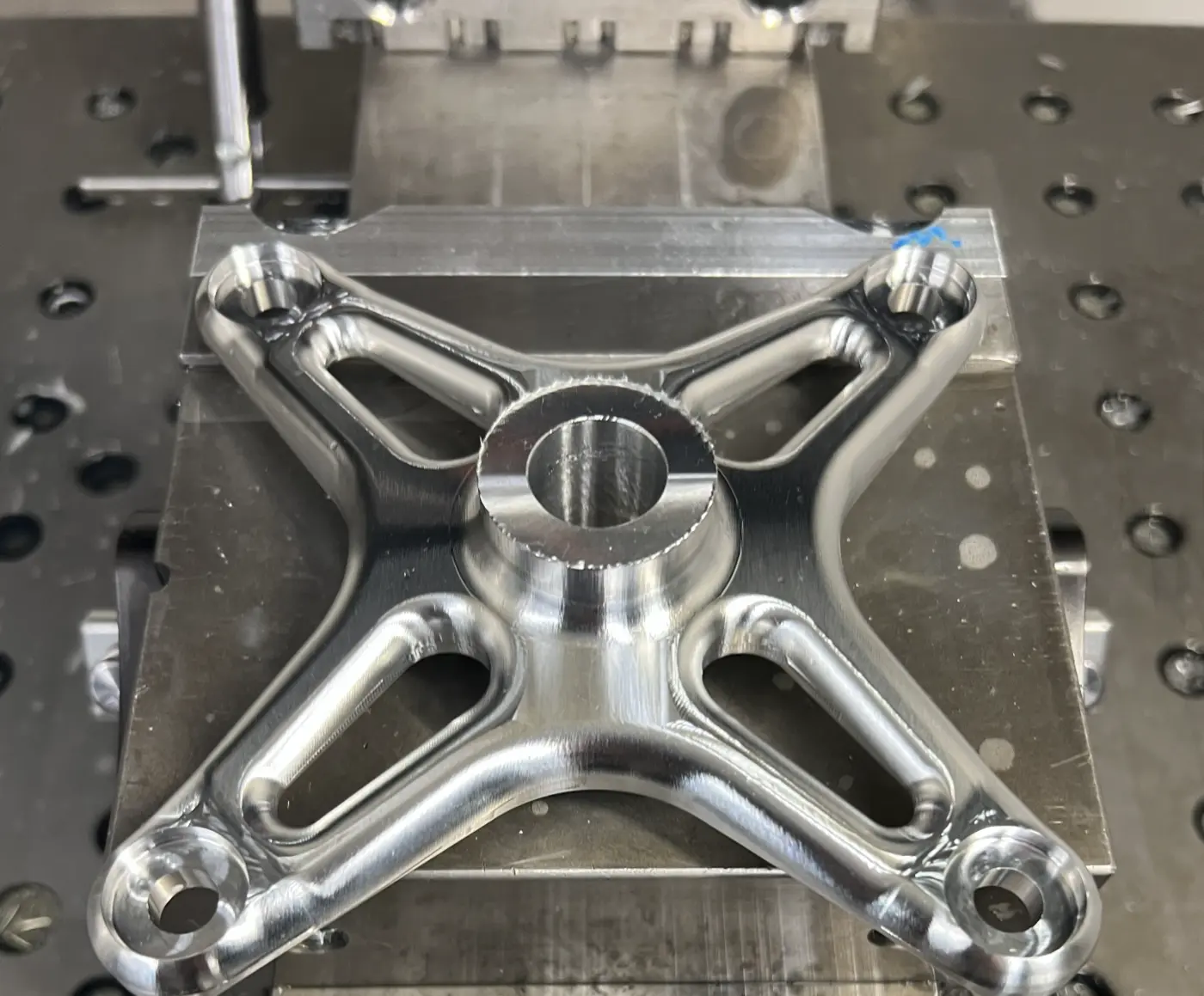
I machined the rear hub in two CNC operations. The first setup machined one side from raw stock. For the second operation, I designed custom soft jaws that matched the hub’s profile, held the finished side securely, and left the opposite side accessible for machining.
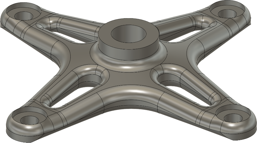
First-Side Machining
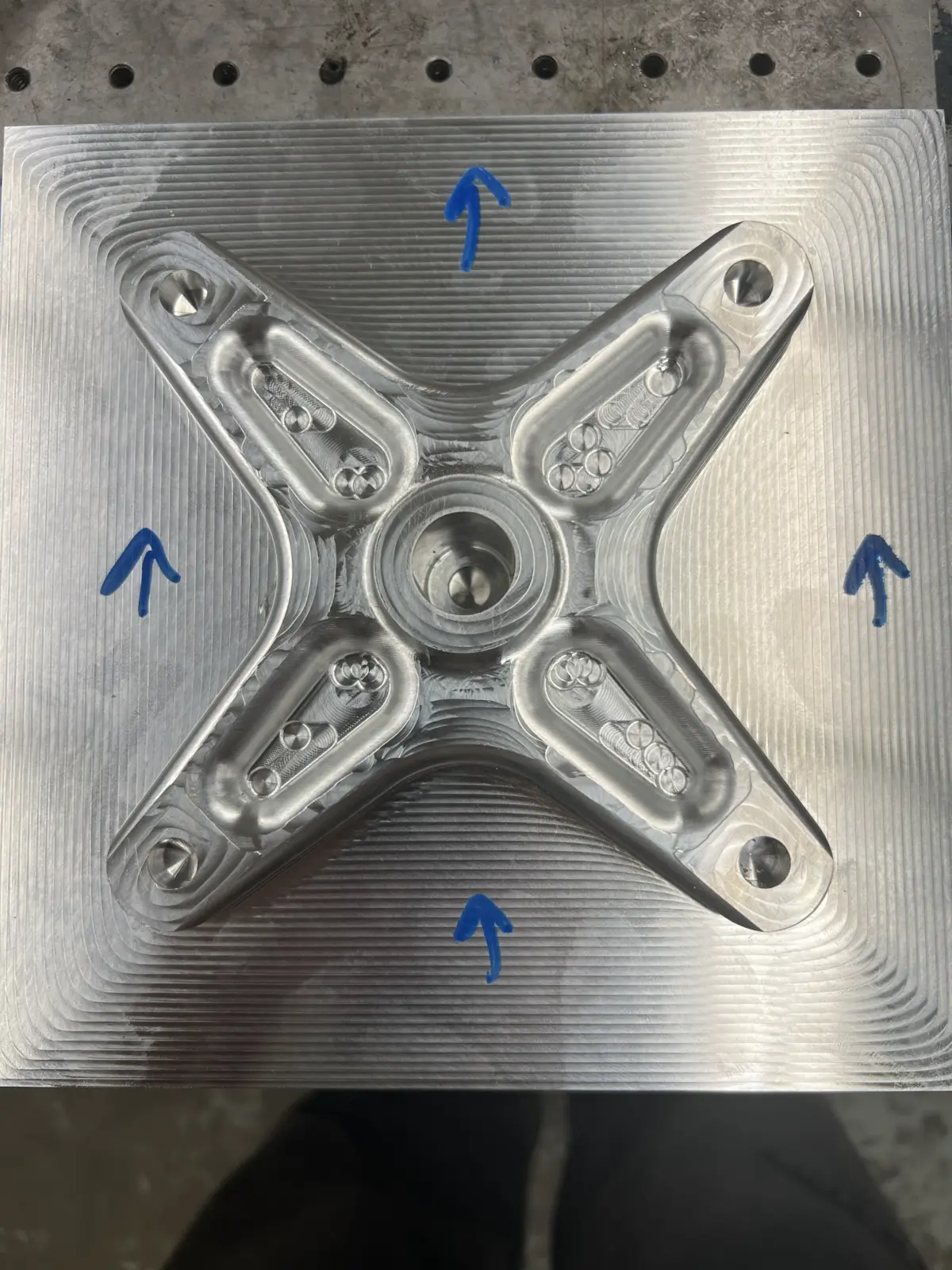
Custom Soft-Jaw Setup
Machining Setup
Tooling Used
| Tool icon | Tool name | Size |
|---|---|---|
 |
403 · Aluminum End Mill (R0.03″) | Ø 1/2″ |
 |
404 · Aluminum End Mill (R0.03″) | Ø 1/4″ |
 |
204 · 140° Drill | Ø 3/8″ |
 |
200 · 140° Drill | Ø 1/4″ |
 |
602 · Aluminum Face Mill | Ø 3″ |
CNC Machining · 6061-T6 Aluminum
Rear Upright
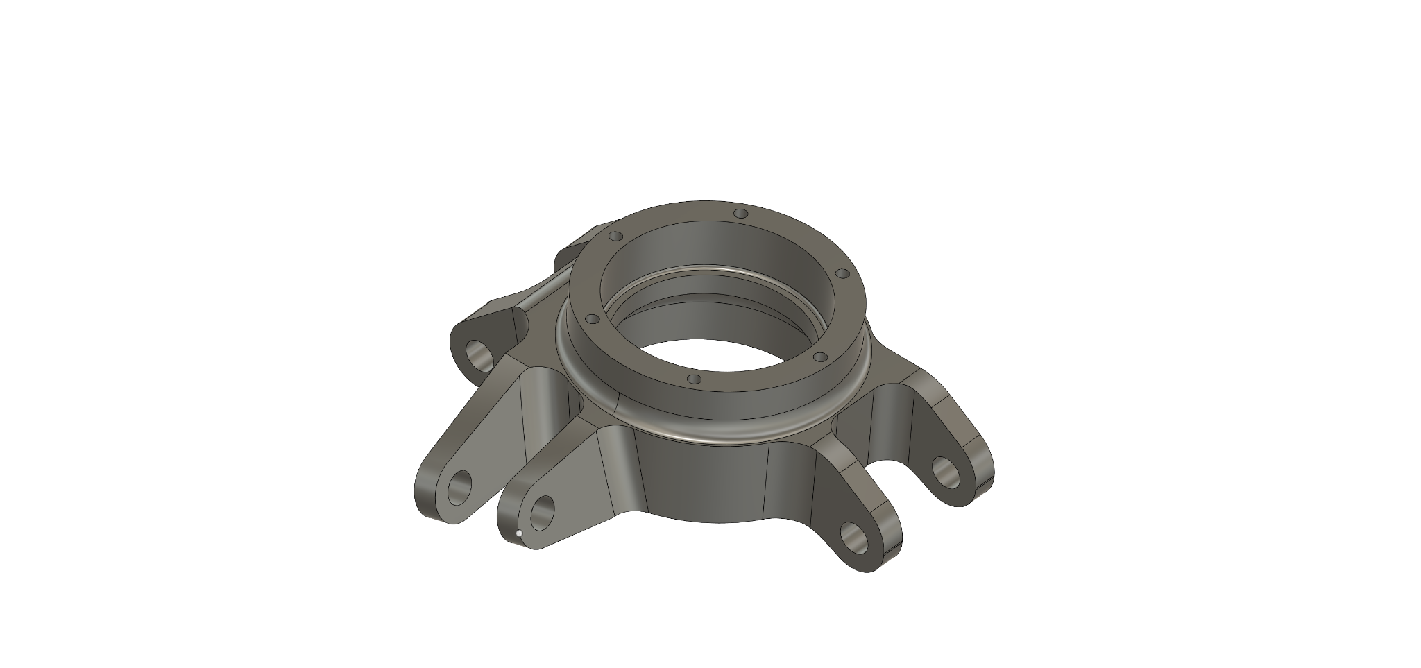
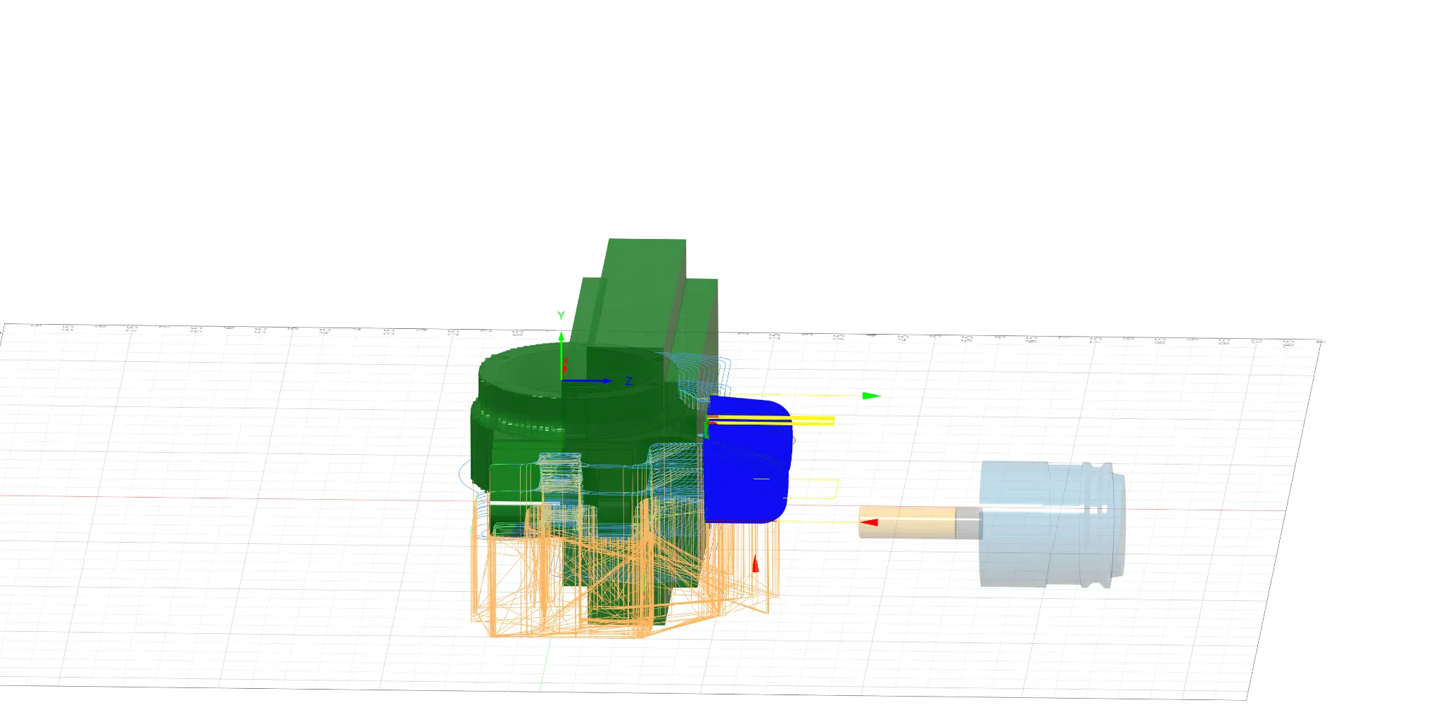
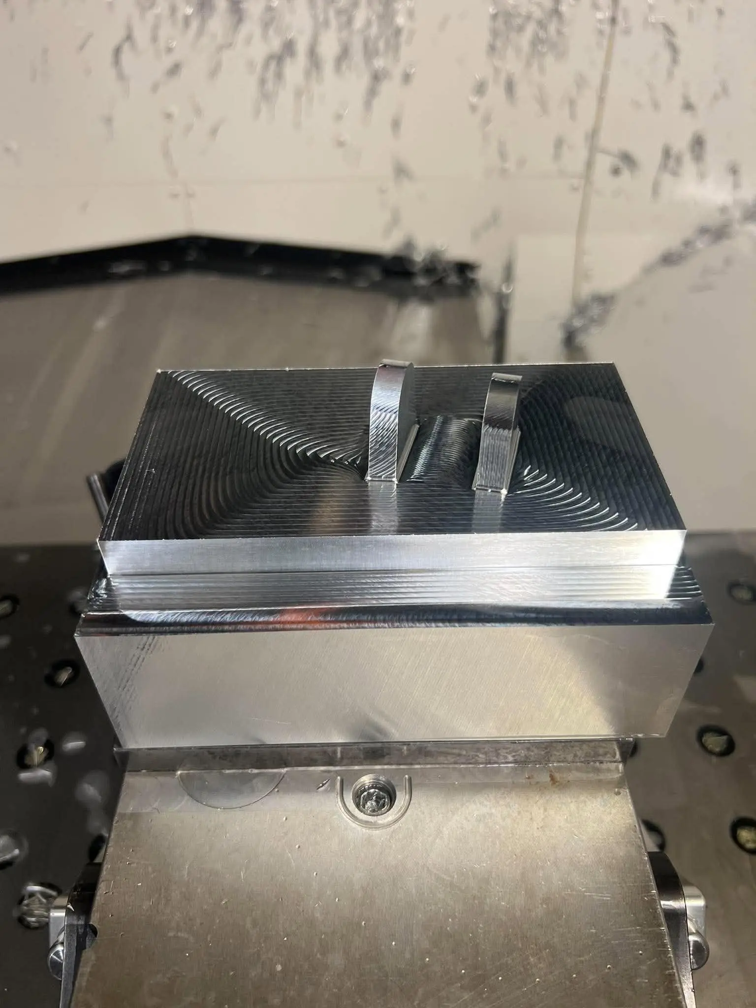
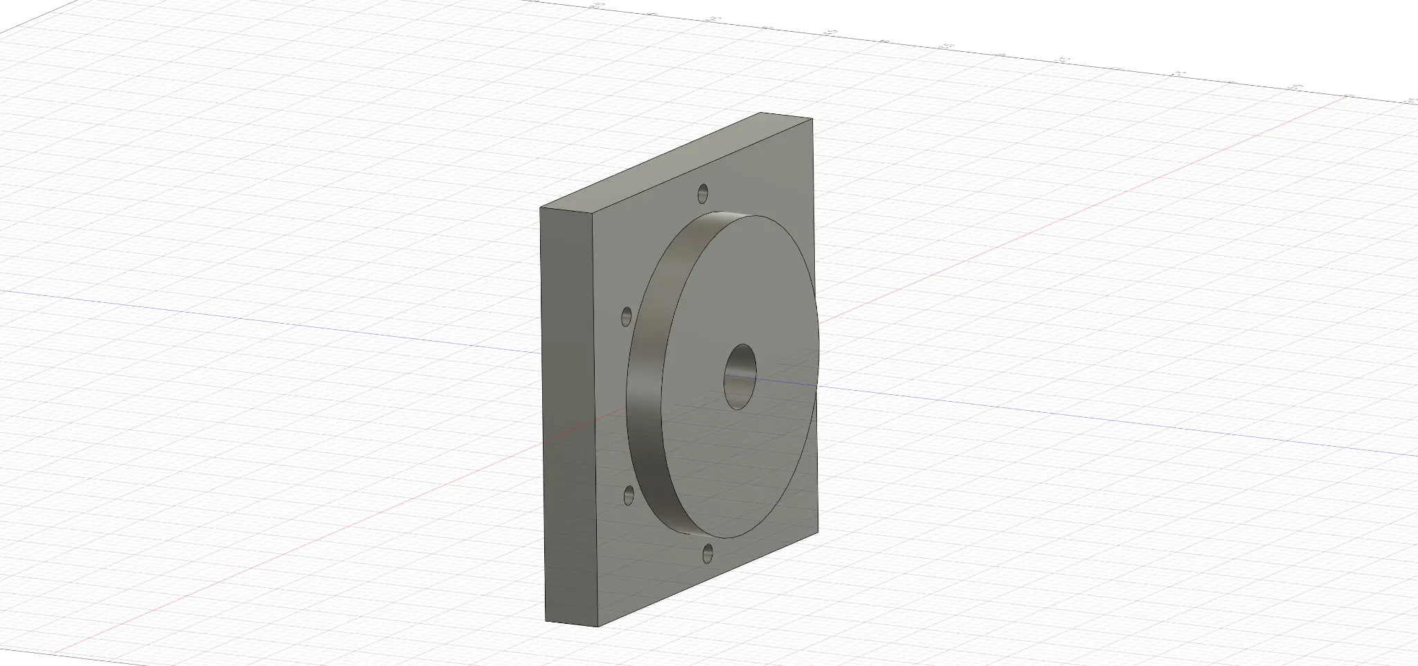
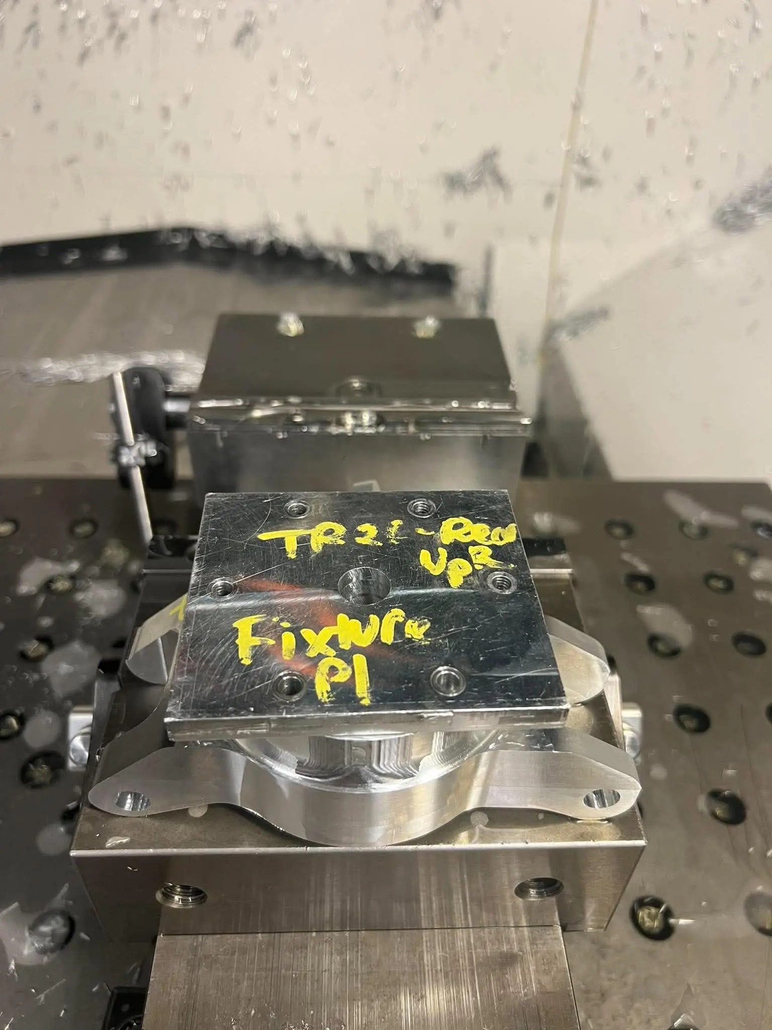
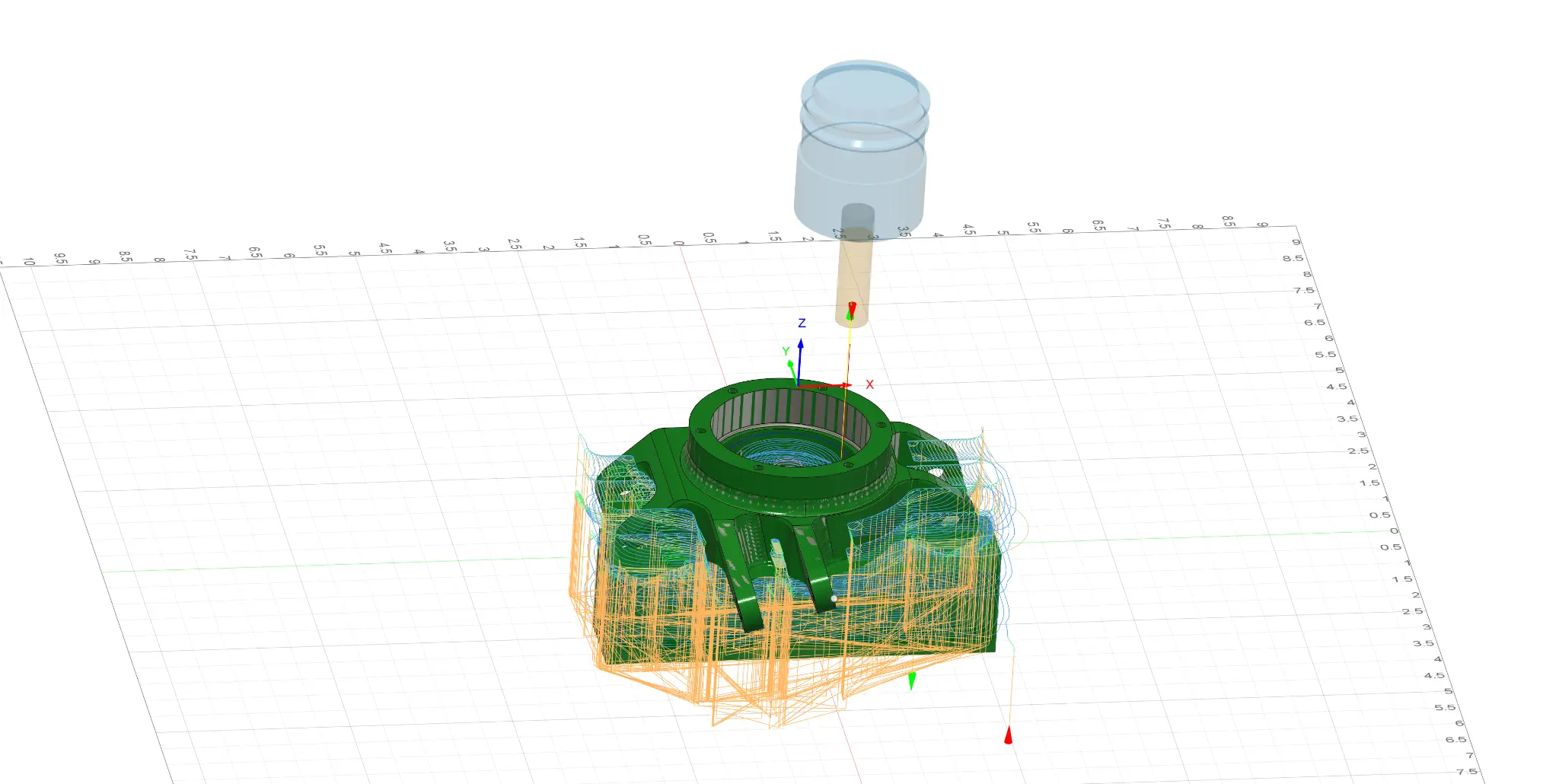
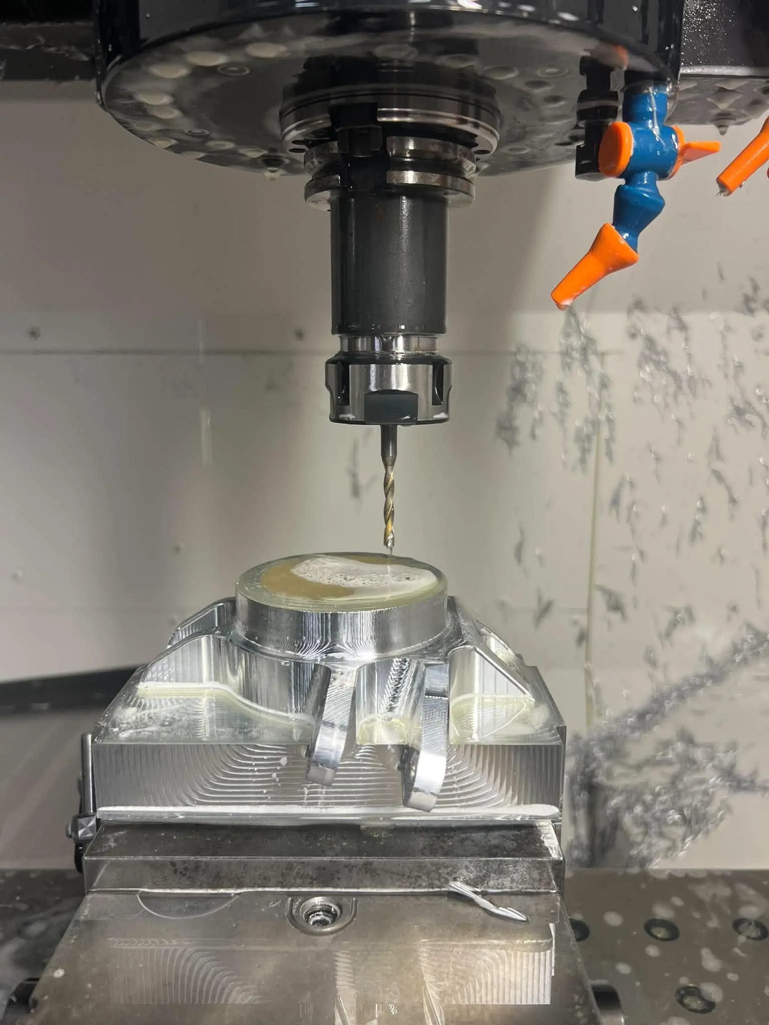
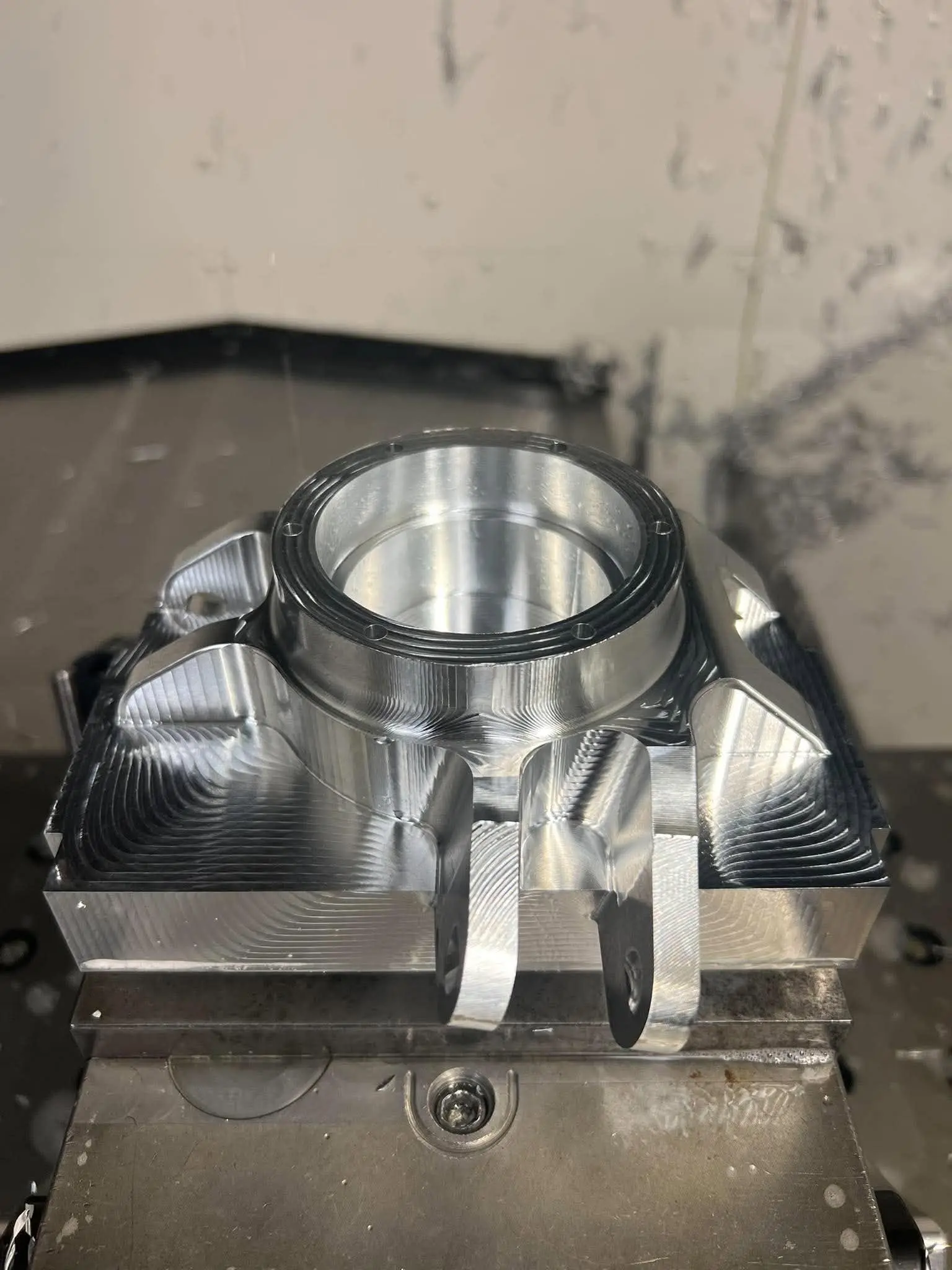
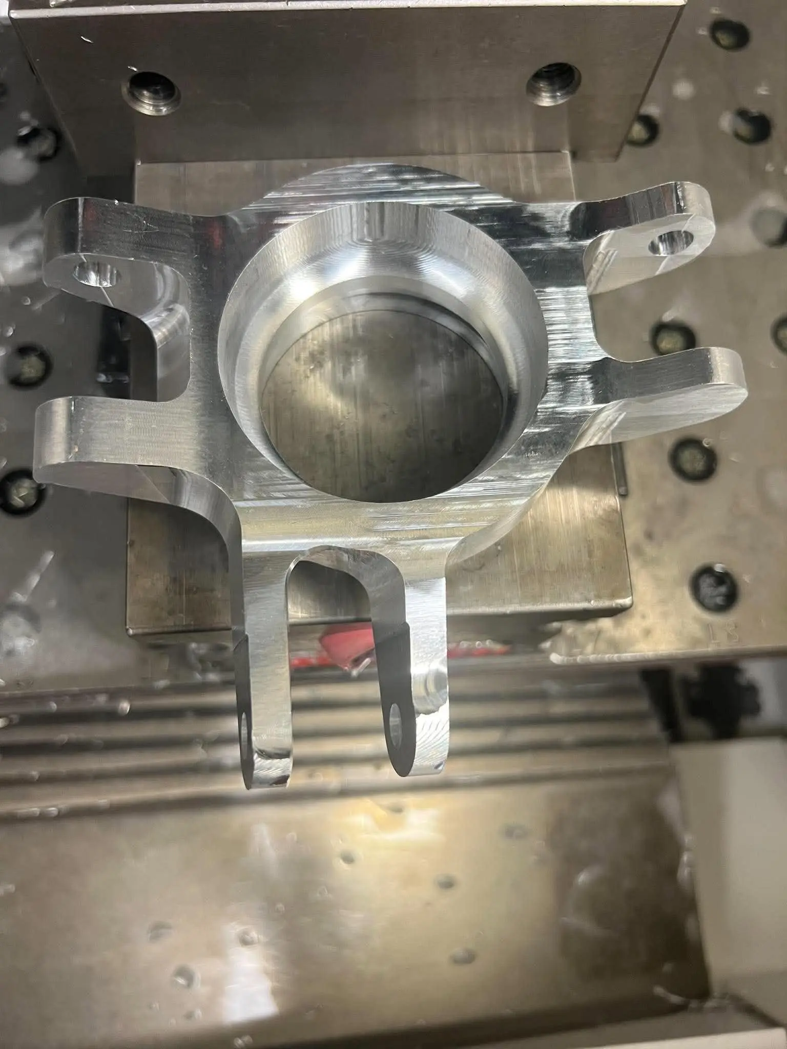
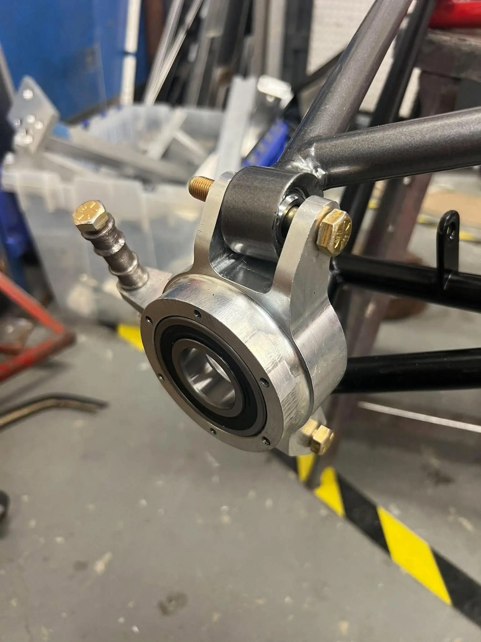
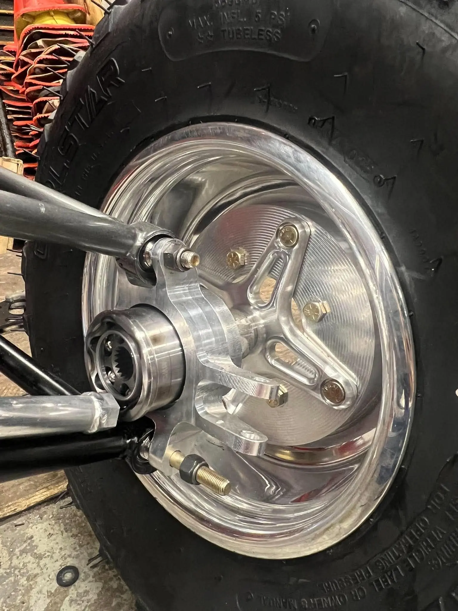
I machined the rear upright through three CNC operations, with each setup exposing a different side of the part. Operations 1 and 2 formed the main geometry, then a custom fixture plate held the upright for the final drilling and finishing work. The completed part was installed in the car’s rear suspension.
First-Side Machining
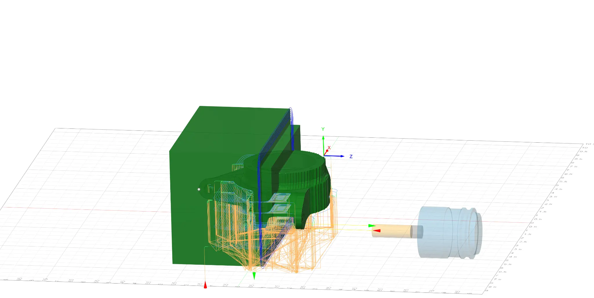
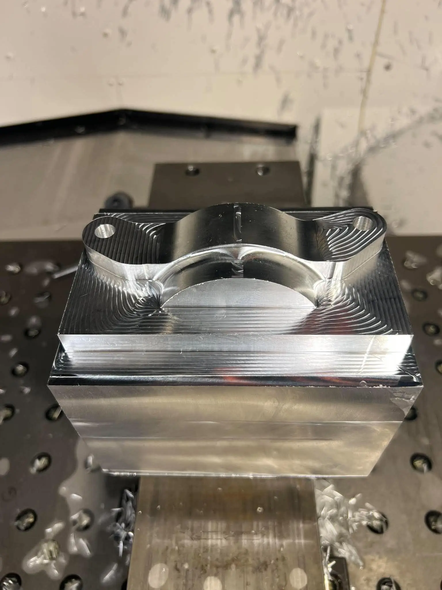
Second-Side Machining
Custom Fixture Plate
Final Machining & Drilling
From Machine to Suspension
Machining Setup
Tooling Used
| Tool icon | Tool name | Size |
|---|---|---|
|
403 · Aluminum End Mill (R0.03″) | Ø 1/2″ |
|
204 · 140° Drill | Ø 3/8″ |
|
602 · Aluminum Face Mill | Ø 3″ |
 |
202 · 140° Drill (#10–24) | Ø 0.1496″ (3.8 mm) |
CNC Machining · 6061-T6 Aluminum
Front Hub
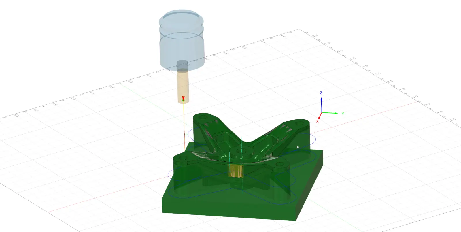
I machined the front hub in two CNC operations. Operation 1 formed the main geometry from raw 6061-T6 aluminum. I then designed custom soft jaws around the finished side of the hub, creating a secure and accurate setup for machining the remaining features in Operation 2.
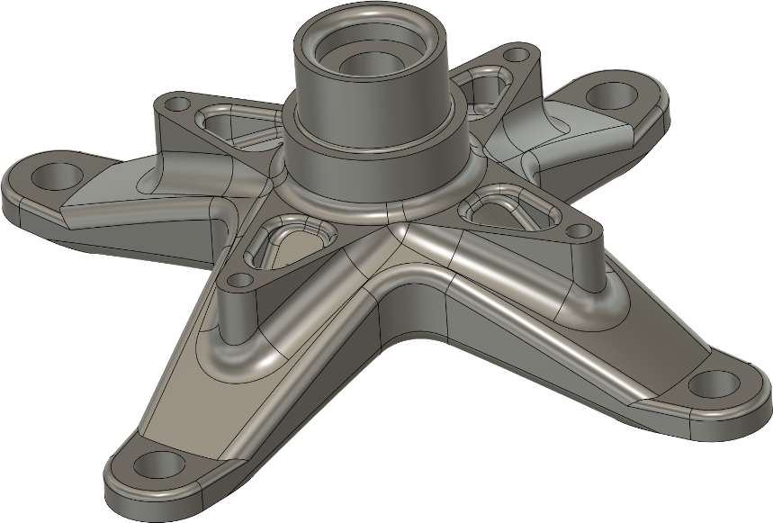
First-Side Machining
Custom Soft-Jaw Setup
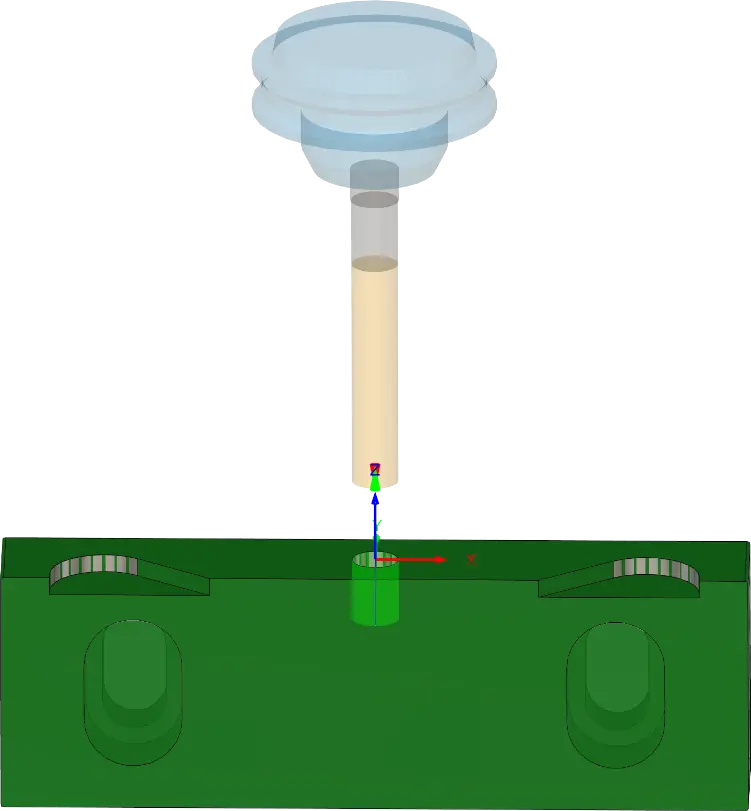
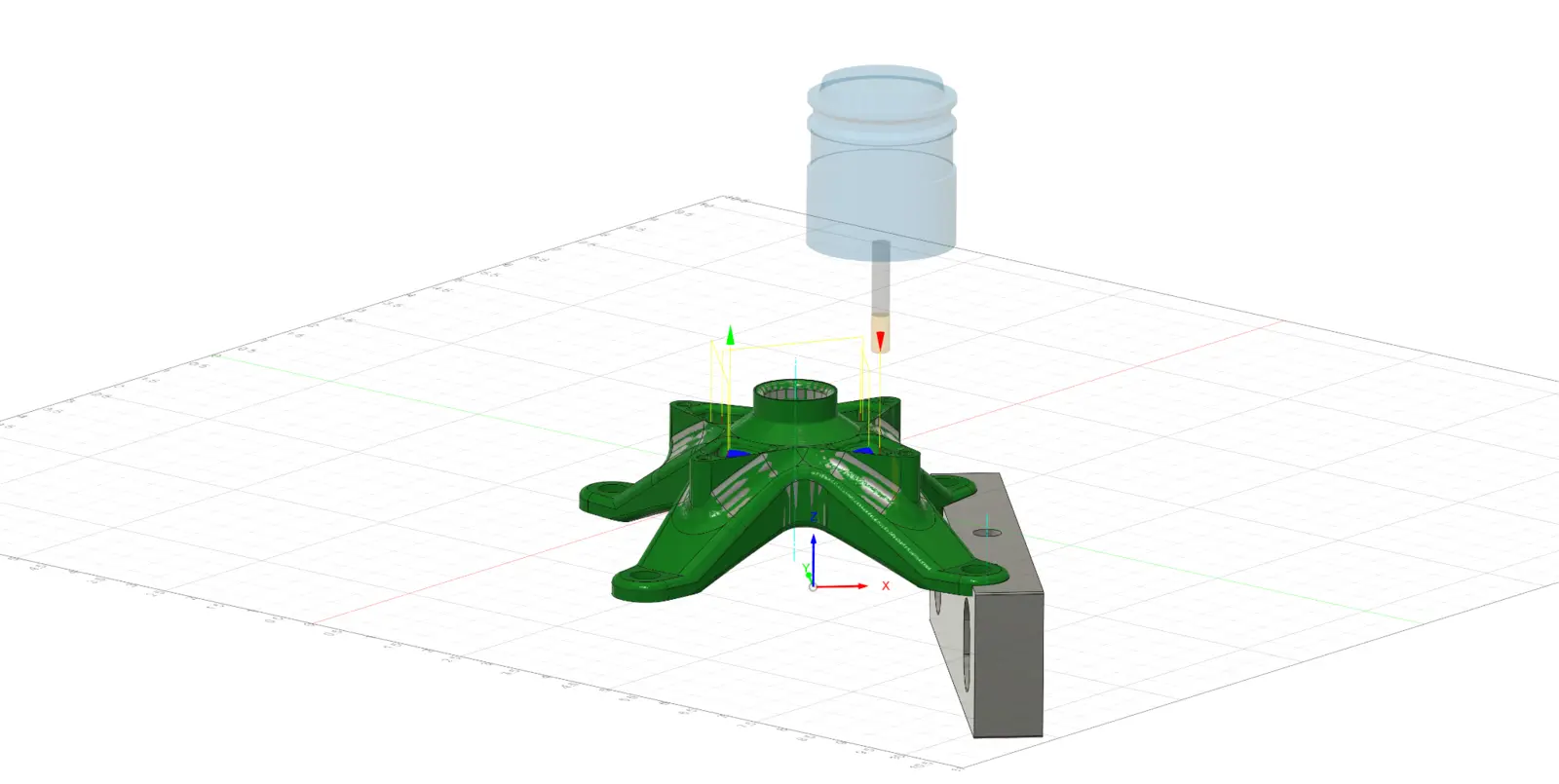
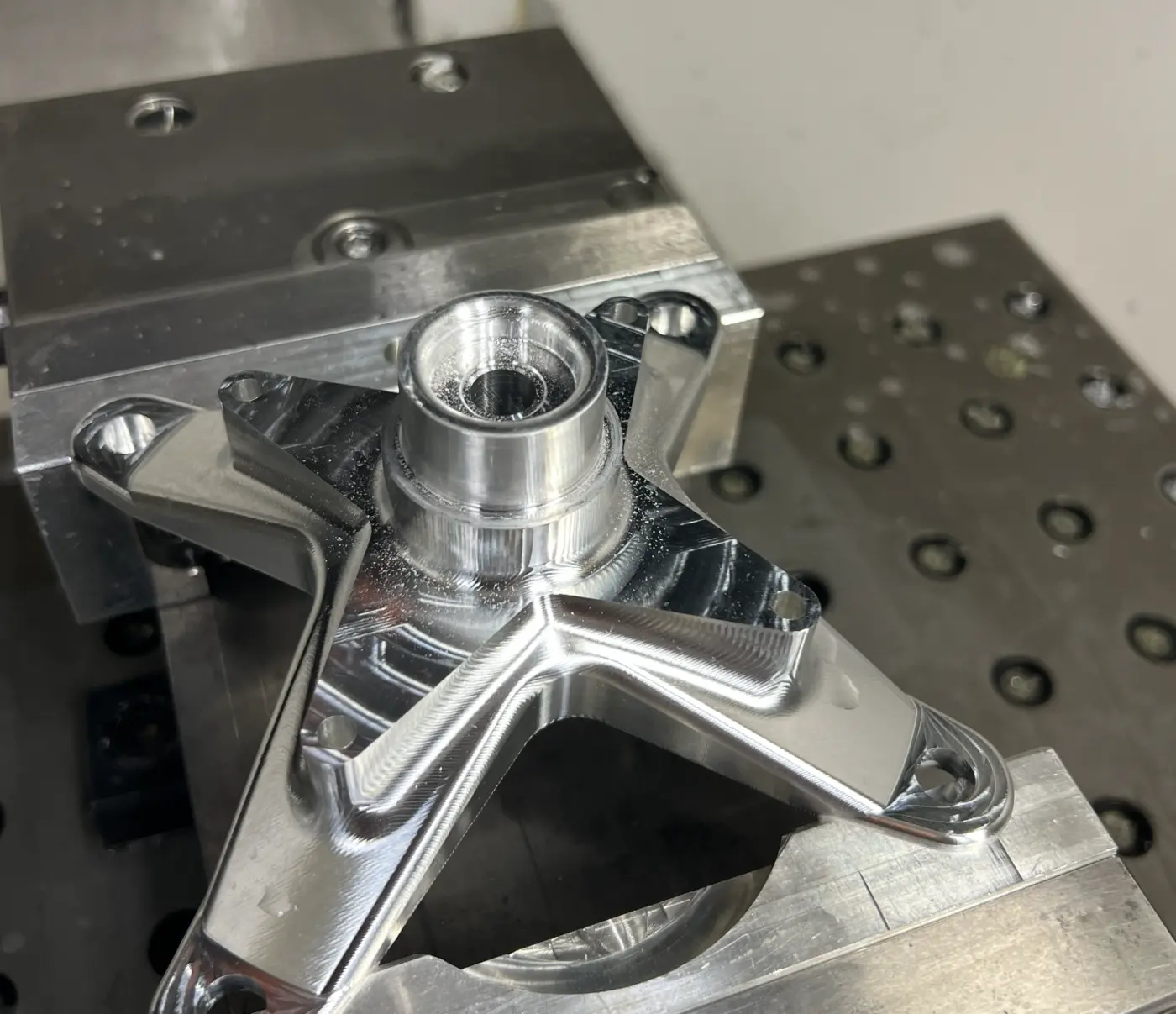
Machining Setup
Tooling Used
| Tool icon | Tool name | Size |
|---|---|---|
|
403 · Aluminum End Mill (R0.03″) | Ø 1/2″ |
|
404 · Aluminum End Mill (R0.03″) | Ø 1/4″ |
 |
412 · Long-Reach Aluminum End Mill (R0.03″) | Ø 3/8″ |
|
204 · 140° Drill | Ø 3/8″ |
 |
201 · 140° Drill (#7) | Ø 0.201″ (5.106 mm) |
|
602 · Aluminum Face Mill | Ø 3″ |
CNC Machining · 6061-T6 Aluminum
Front Upright
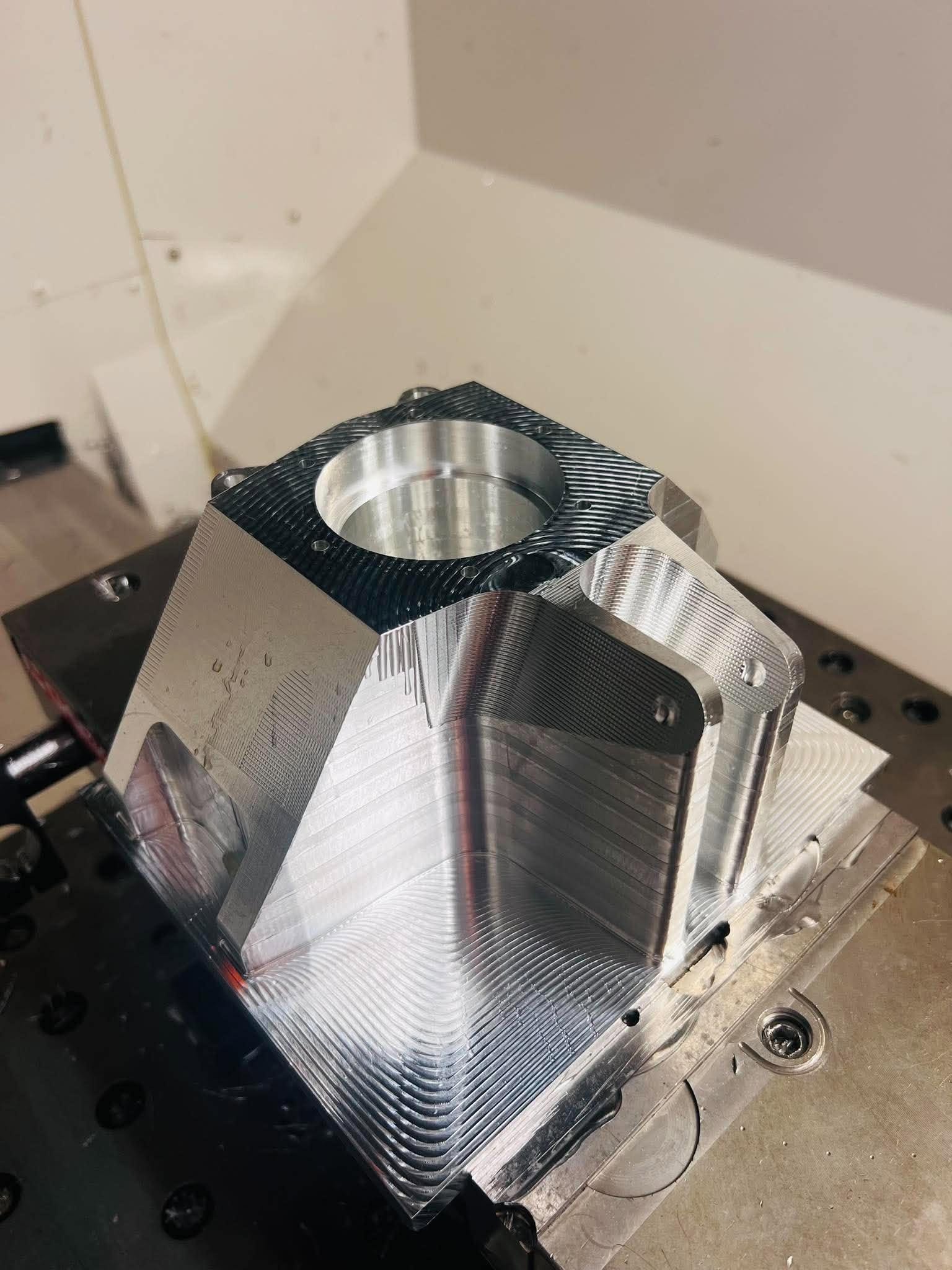
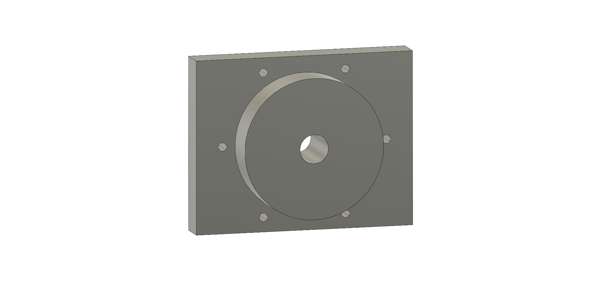
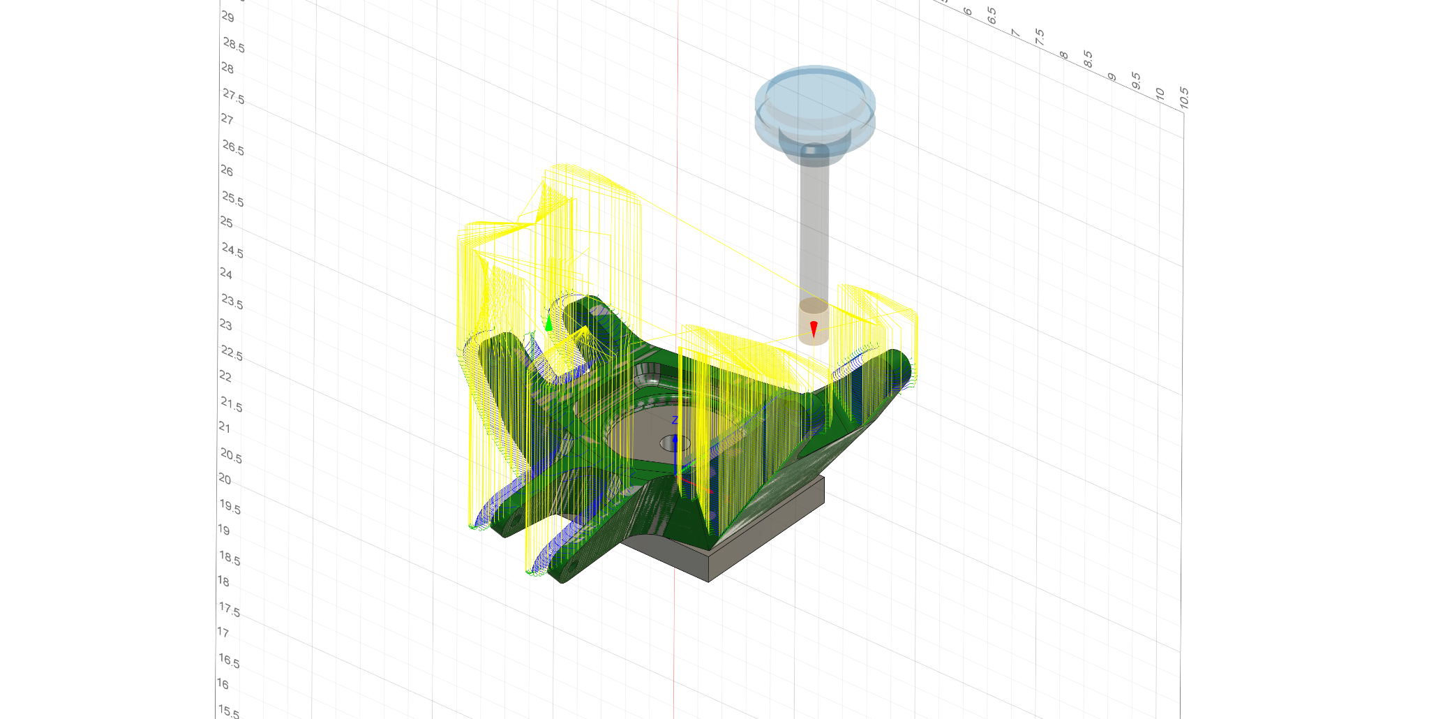
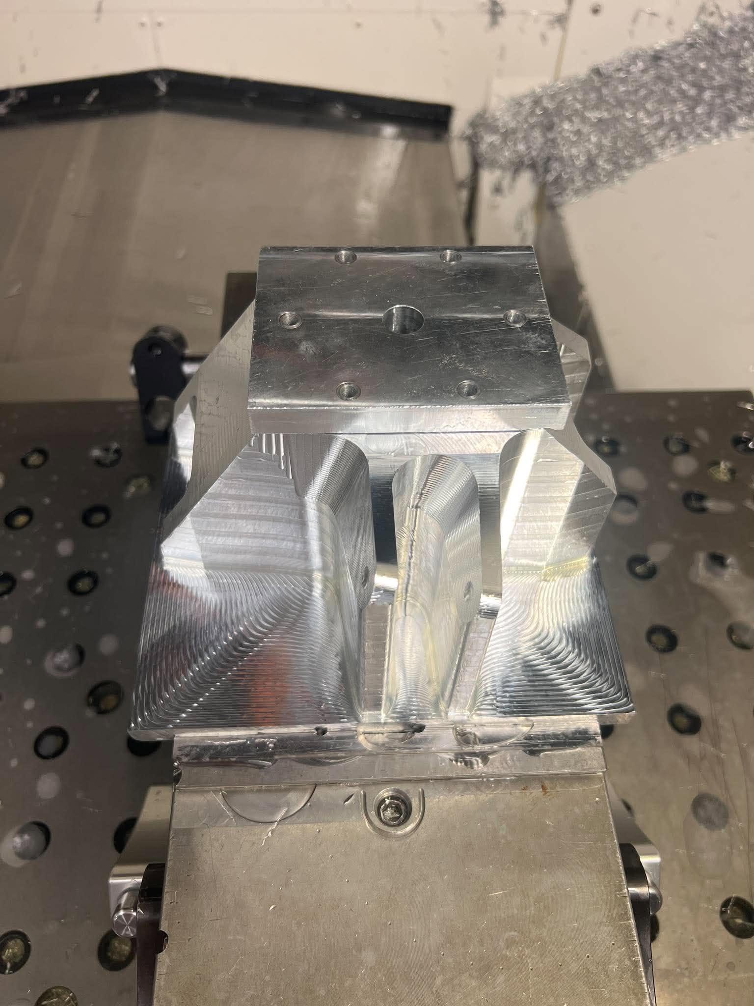
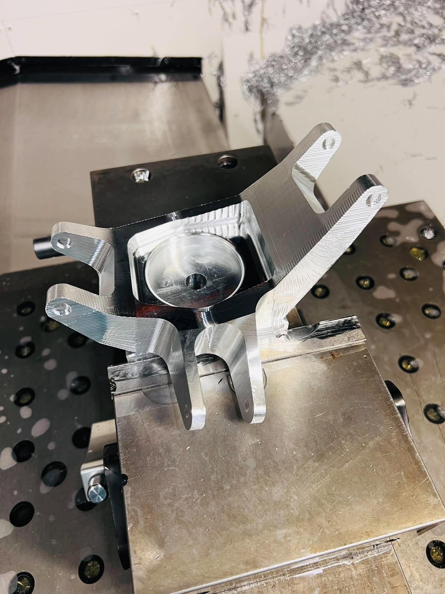
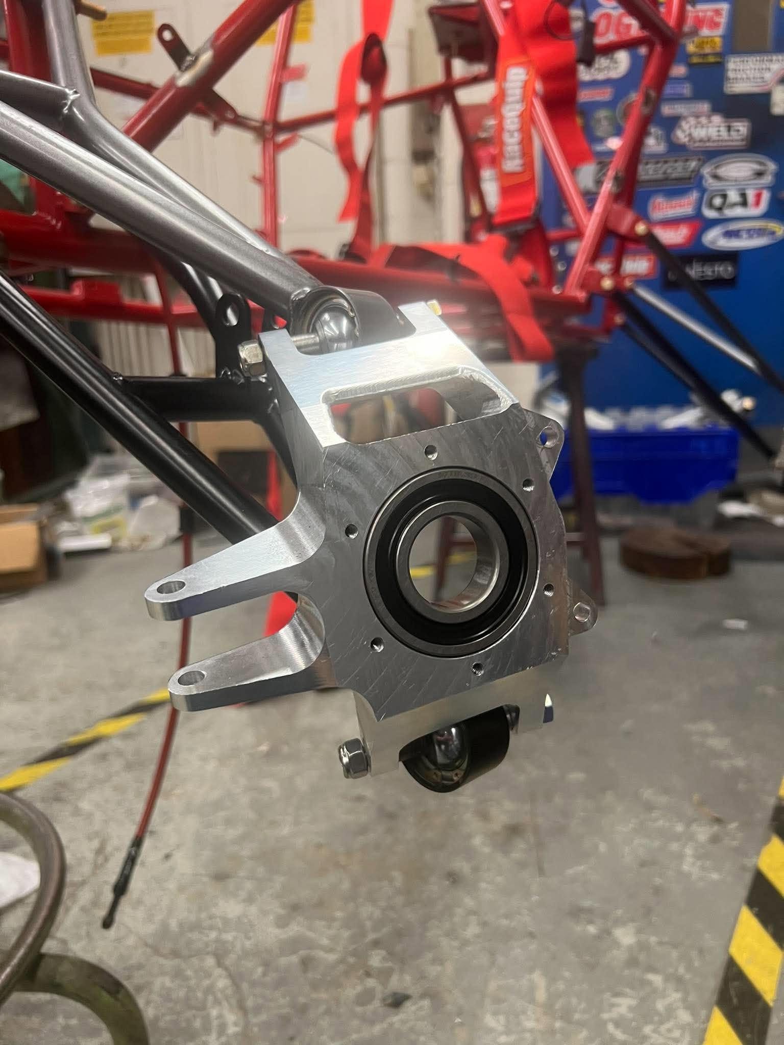
Starting with a 7″ × 6″ × 4″ block of 6061-T6 aluminum, I machined the front upright in two CNC operations. The first operation removed most of the stock and formed the primary geometry. I then designed a dedicated fixture plate to hold the part for the second operation, finished the remaining features, and installed the completed upright on the Baja car.
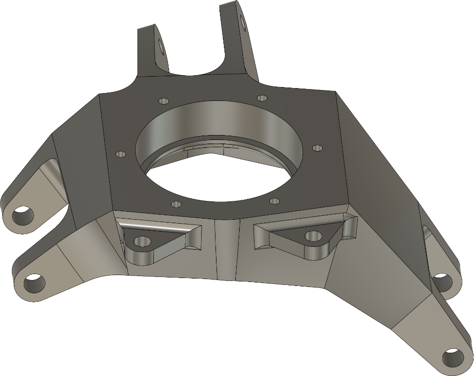
Aluminum Stock
6061-T6 Aluminum · 7″ × 6″ × 4″
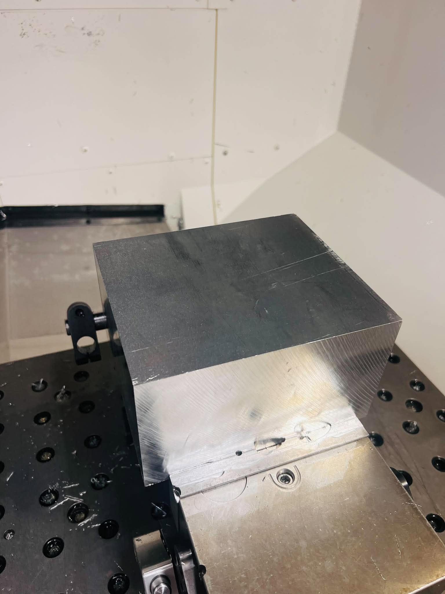
First-Side Machining
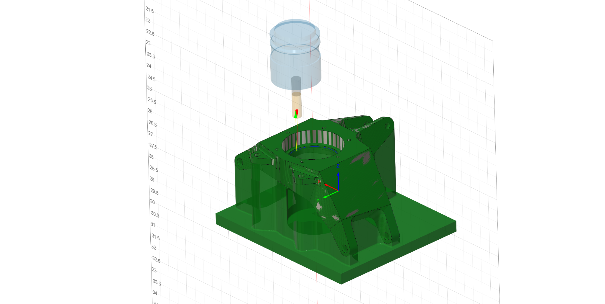
Custom Fixture-Plate Setup
From Machine to Car
Machining Setup
Tooling Used
| Tool icon | Tool name | Size |
|---|---|---|
 |
405 · Aluminum End Mill (R0.06″) | Ø 3/8″ |
 |
406 · Long-Reach Aluminum End Mill (R0.03″) | Ø 1/2″ |
 |
501 · Aluminum Ball-Nose End Mill | Ø 3/8″ |
|
202 · 140° Drill (#10–24) | Ø 0.1496″ (3.8 mm) |
 |
203 · 140° Drill (F) | Ø 0.257″ (6.528 mm) |